boost analysis...
Intro by James N
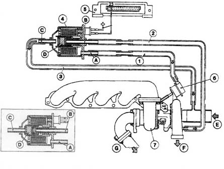
The Boost control system on the 20v turbo consists of 3 main components. The turbocharger wastegate (6), the boost control solenoid (4) and the Electronic control unit (5).
Normally the wastegate is connected straight to the compressor housing and is configured so at a preset boost level (governed by the actuator spring pressure) the wastegate will open and allow exhaust gas to exit the engine without driving the exhaust turbine and so causes the turbo to slow down, decreasing boost pressure. In this application the boost solenoid allows the ECU to control the boost by bleeding off air pressure to the turbocharger wastegate which allows it to stay shut longer and the turbocharger can develop higher boost pressure than the wastegate actuator spring pressure would normally allow. How does it do this ?
This is the boost control solenoid - a small electromechanical device made by Bosch and is situated in front of and below the battery tray.
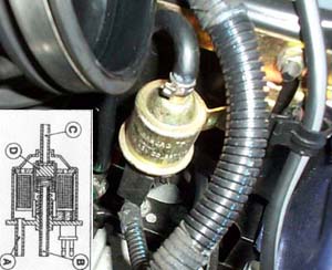
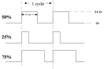
It has 3 pipes connected to it - the top one is the air bleed and connects to the inlet pipe of the turbo, the two connections on the bottom of the valve connect to the compressor housing and wastegate actuator. The electrical connection is to the ECU via two wires. The valve is operated by a PWM signal (pulsed ground), who's duty cycle varies between 0-100%. In this application the operating frequency of the valve is 33Hz (33 Cycles per second). The duty cycle of the waveform is the on time (t-on) / 1 cycle. If the on time was equal to the off time then the duty cycle would be 50%. If the on time was 25% and the off time was 75% then the duty cycle would be 25% and so on. In this application 1 cycle = 30ms.
By regulating the valves duty cycle, the ECU can regulate the boost pressure to match the predetermined value from the map in the ECU. Depending on the amount of boost pressure required, the valve will either increase the amount of boost pressure to the wastegate to lower the boost pressure (opening the wastegate), or, vent boost pressure to the inlet side of the turbocharger to raise charge pressure (allowing the wastegate to remain closed). If the valve should fail, the boost pressure is controlled at a lower value mechanically by the wastegate. Self diagnostics in the ECU recognises two faults; break/short to ground, and short to positive.
Analysis by Spunky M
These are the results of hooking a handheld digital scope to the electronic bleed valve to see how it is controlled whilst driving.
![]() Bleed
valve control global parameters:
Bleed
valve control global parameters:
Wave shape - square pulse
Operating freq - 33Hz
Rise time - 15us
Fall time - 7us
Amplitude - 14.4V
![]() Idle
and off-boost driving:
Idle
and off-boost driving:
Duty cycle - <1%
On-time - 0.2ms
Off-time - 29.8ms
Valve is effectively off (no bleed). This means that turbo actuator is connected
directly to all the inlet manifold pressure and hence a minimum boost would be
achieved if the valve remained in this state with the accelerator floored (it
doesn't).
![]() 4th
gear, floored from 1500rpm:
4th
gear, floored from 1500rpm:
At 1500 rpm:
Duty cycle - >99%
On-time - 29.8ms
Off-time - 0.2ms
Effectively a reversal of the above - the actuator is not connected at all to
the inlet manifold boost pressure which results in as much boost as the turbo
can possibly produce (which isn't that much at 1500rpm - usually around 0.2bar).
![]() At
2500rpm:
At
2500rpm:
Duty
cycle - 70%
On-time - 21ms
Off-time - 9ms
As the boost begins to rise very quickly due to the 100% duty cycle previously,
the valve very quickly responds and reduces to around 70% duty cycle. This is
the overboost condition resulting in about 1.2bar of boost in my case.
![]() 3000rpm
onwards:
3000rpm
onwards:
Duty
cycle - 50%
On-time - 15ms
Off-time - 15ms
This seems to be the 'operating point' for the valve. Gives around 0.9 - 1bar of
boost.
There are a few other conditions which you might find interesting:
![]() Accelerator
floored from 1500rpm in 2nd gear:
Accelerator
floored from 1500rpm in 2nd gear:
As 4th gear but as revs begin to rise quickly past 3000rpm, duty cycle settles
at around 30% rather than 50% (dynamic boost limit calculated on rate of revs
increase). The duty cycle is then reduced further slightly to around 25% as you
approach redline. This helps the boost to drop off at high rpm which also helps
to confuse my possible weak actuator spring theory! Bolx.
Everything just happens too fast in 1st to see whats going on. Just watching the
thing operating whilst driving, you can see the ECU trying to make sense of all
it's inputs from various sensors and controlling the valve - it dosn't do a very
good job most of the time, and the duty cycle change on the valve is not always
consistent and takes too long.